Assalamualaikum Wr.Wb Yu-huuu... kali ini aku sahabat husen akan menyebarkan Soal CCNA PT Practice Skill Exam 2018
 Pada Soal CCNA PT Practice Skill Exam, terdapat 2 buah type model soal ya sahabat sanggup dilihat dari penamaan device nya jangan lihat bagan nya.
Untuk mengerjakan soal ini harus update sebagai berikut :
1. Update Java
2. Update Adobe Flash
3. Install Cisco Packet Tracer apabila belum menginstal

A few things to keep in mind while completing this activity:
1. Do not use the browser Back button or close or reload any exam windows during the exam.
2. Do not close Packet Tracer when you are done. It will close automatically.
3. Click the Submit Assessment button in the browser window to submit your work.
Introduction
In this assessment, you will configure devices in an IPv4/IPv6 network. For the sake of time, you will not be asked to perform all configurations on all network devices as you may be required to do in a real network or other assessment. Instead, you will use the skills and knowledge that you have learned in the labs in this course to configure the Building 1 router. In addition, you will address the hosts on two LANs with IPv4 and IPv6 addresses, activate and address the management interface of the Second Floor Switch, and back up a device configuration to a TFTP server.
You will receive one of several topologies.
You are not required to configure the First Floor Switch, and you will not be able to access it in this practice skills assessment activity.
All IOS device configurations should be completed from a direct terminal connection to the device console. In addition, many values that are required to complete the configurations have not been given to you. In those cases, create the values that you need to complete the requirements. For values that have been supplied to you, they must be entered exactly as they appear in order for you to get full credit for your configuration.
You will practice and be assessed on the following skills:
• Configuration of initial IOS device settings
• Design and calculation of IPv4 addressing
• Configuration of IOS device interfaces including IPv4 and IPv6 addressing when appropriate
• Addressing of network hosts with IPv4 and IPv6 addresses
• Enhancing device security, including configuration of the secure transport protocol for remote device configuration
• Configuration of a switch management interface
Requirements by device:
Building 1 router:
• Configuration of initial router settings
• Interface configuration and IPv4 and IPv6 addressing
• Device security enhancement or device hardening
• Secure transport for remote configuration connections as covered in the labs
• Backup of the configuration file to a TFTP server
Second Floor Switch:
• Enabling basic remote management by Telnet
PC and Server hosts:
• IPv4 full addressing
• IPv6 addressing
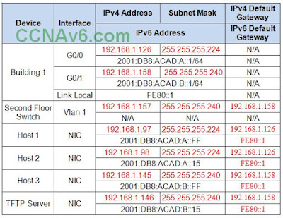
Addressing Table
 Instructions
Step 1: Determine the IP Addressing Scheme.
Design an IPv4 addressing scheme and complete the Addressing Table based on the following requirements. Use the table to help you organize your work.
 a. Subnet the 192.168.1.0/24 network to provide 30 host addresses per subnet while wasting the fewest addresses.
b. Assign the fourth subnet to the First Floor LAN.
c. Assign the last network host address (the highest) in this subnet to the G0/0 interface on Building 1. (192.168.1.126)
d. Starting with the fifth subnet, subnet the network again so that the new subnets will provide 14 host addresses per subnet while wasting the fewest addresses.
e. Assign the second of these new 14-host subnets to the Second Floor LAN.
f. Assign the last network host address (the highest) in the Second Floor LAN subnet to the G0/1 interface of the Building 1 router. (192.168.1.158)
g. Assign the second to the last address (the second highest) in this subnet to the VLAN 1 interface of the Second Floor Switch. (192.168.1.157)
h. Configure addresses on the hosts using any of the remaining addresses in their respective subnets.
Step 2: Configure the Building 1 Router.
a. Configure the Building 1 router with all initial configurations that you have learned in the course so far:
• Configure the router hostname: Middle
• Protect device configurations from unauthorized access with the encrypted privileged exec password.
• Secure all access lines into the router using methods covered in the course and labs.
• Require newly-entered passwords must have a minimum length of 10 characters.
• Prevent all passwords from being viewed in clear text in device configuration files.
• Configure the router to only accept in-band management connections over the protocol that is more secure than Telnet, as was done in the labs. Use the value 1024 for encryption key strength.
• Configure local user authentication for in-band management connections. Create a user with the name netadmin and a secret password of Cisco_CCNA5 Give the user the highest administrative privileges. Your answer must match these values exactly.
b. Configure the two Gigabit Ethernet interfaces using the IPv4 addressing values you calculated and the IPv6 values provided in the addressing table.
• Reconfigure the link local addresses to the value shown in the table.
• Document the interfaces in the configuration file.
Step 3: Configure the Second Floor Switch.
Configure Second Floor Switch for remote management over Telnet.
Step 4: Configure and Verify Host Addressing.
a. Use the IPv4 addressing from Step 1 and the IPv6 addressing values provided in the addressing table to configure all host PCs with the correct addressing.
b. Use the router interface link-local address as the IPv6 default gateways on the hosts.
Step 5: Backup the Configuration of the Building 1 Router to TFTP.
a. Complete the configuration of the TFTP server using the IPv4 addressing values from Step 1 and the values in the addressing table.
b. Backup the running configuration of Building 1 to the TFTP Server. Use the default file name.


 Kemudian sehabis terhubung Klik Host 1 > Tab Dekstop > Terminal > Klik Ok

kemudian ketikan config berikut ini :
Caranya Hubungkan terlebih dahulu PC Host 3 ke Switch Second Floor Switch memakai kabel console
 Sama untuk menghubungkannya ibarat cara di atas, hubungkan Host 3 dengan kabel Console dengan menentukan RS 232 sedangkan pada Switch pilih Console. Selanjutnya Klik PC Host 3 > Tab Dekstop > Terminal > Klik Ok. Ketikan Config dibawah ini.
*Ping 192.168.1.97
*Ping 192.168.1.98
*Ping 192.168.1.145
*Ping 192.168.1.146
Apabila ada pemberitahun Reply bla bla maka itu sudah terhubung dan berhasil.
4. Selesai TYPE A.


a. Subnet the 192.168.1.0/24 network to provide 30 host addresses per subnet while wasting the fewest addresses.
b. Assign the fourth subnet to the IT Department LAN.
c. Assign the last network host address (the highest) in this subnet to the G0/0 interface on Town Hall/CS Department . (192.168.1.126)
d. Starting with the fifth subnet, subnet the network again so that the new subnets will provide 14 host addresses per subnet while wasting the fewest addresses.
e. Assign the second of these new 14-host subnets to the Administration LAN.
f. Assign the last network host address (the highest) in the Administration LAN subnet to the G0/1 interface of the Town Hall router. (192.168.1.158)
g. Assign the second to the last address (the second highest) in this subnet to the VLAN 1 interface of the Administration Switch (or LAB 214-A Switch). (192.168.1.157)
h. Configure addresses on the hosts using any of the remaining addresses in their respective subnets.
Step 2: Configure the Town Hall router (or CS Department Router).
a. Configure the Town Hall router (or CS Department Router) with all initial configurations that you have learned in the course so far:
• Configure the router hostname: Middle
• Protect device configurations from unauthorized access with the encrypted privileged exec password.
• Secure all access lines into the router using methods covered in the course and labs.
• Require newly-entered passwords must have a minimum length of 10 characters.
• Prevent all passwords from being viewed in clear text in device configuration files.
• Configure the router to only accept in-band management connections over the protocol that is more secure than Telnet, as was done in the labs. Use the value 1024 for encryption key strength.
• Configure local user authentication for in-band management connections. Create a user with the name netadmin and a secret password of Cisco_CCNA5 Give the user the highest administrative privileges. Your answer must match these values exactly.
b. Configure the two Gigabit Ethernet interfaces using the IPv4 addressing values you calculated and the IPv6 values provided in the addressing table.
• Reconfigure the link local addresses to the value shown in the table.
• Document the interfaces in the configuration file.
Step 3: Configure the Administration Switch (or LAB 214-A Switch).
Configure Administration Switch (or LAB 214-A Switch) for remote management over Telnet.
Step 4: Configure and Verify Host Addressing.
a. Use the IPv4 addressing from Step 1 and the IPv6 addressing values provided in the addressing table to configure all host PCs with the correct addressing.
b. Use the router interface link-local address as the IPv6 default gateways on the hosts.
Step 5: Backup the Configuration of the Town Hall router (or CS Department Router) to TFTP.
a. Complete the configuration of the TFTP server using the IPv4 addressing values from Step 1 and the values in the addressing table.
b. Backup the running configuration of Town Hall (or CS Department) to the TFTP Server. Use the default file name.
1). Reception Host (or 124-1)
IPv4 192.168.1.97 255.255.255.224
GWv4 192.168.1.126
IPv6 2001:DB8:ACAD:A::FF/64
GWv6 FE80::1
2). Operator Host (or 124-5)
IPv4 192.168.1.98 255.255.255.224
GWv4 192.168.1.126
IPv6 2001:DB8:ACAD:A::15/64
GWv6 FE80::1
3). IT Host (or 214-1)
IPv4 192.168.1.145 255.255.255.240
GWv4 192.168.1.158
IPv6 2001:DB8:ACAD:B::FF/64
GWv6 FE80::1
4). TFTP Server
IPv4 192.168.1.146 255.255.255.240
GWv4 192.168.1.158
IPv6 2001:DB8:ACAD:B::15/64
GWv6 FE80::1
 Kemudian Klik PC ( 124-1 ) > Tab Dekstop > Terminal > Klik Ok. Ketikan config dibawah ini dengan benar.
3. Konfigurasi Administration Switch (or LAB 214-A Switch) Melalui PC Client (214-1)
Caranya Hubungkan terlebih dahulu PC Client (214-1) ke Administration Switch (or LAB 214-A Switch) memakai kabel console. Caranya sama ibarat di atas ya menghubungkannya.
 Selanjutnya Klik PC Client ( 214-1 ) > Tab Dekstop > Terminal > Klik Ok. Selanjutnya ketik config berikut ini dengan benar.
Terakhir uji koneksi denga melaksanakan Ping di Server TFTP atau di PC Client mana saja bebas ke IP Address berikut :
*Ping 192.168.1.97
*Ping 192.168.1.98
*Ping 192.168.1.145
*Ping 192.168.1.146
Apabila ada pemberitahun Reply bla bla maka itu sudah terhubung dan berhasil.
4. Selesai TYPE B.
Sekian Soal CCNA PT Practice Skill Exam 2018 supaya membantu sahabat sekalian, mohon maaf apabila ada kesalahan dalam pengetikan dan terimakasih telah mengunjungi. Apabila sahabat ingin bertanya sanggup contact saya. Pepatah bilang “Malu bertanya sesat di jalan” jadi jangan aib bertanya ya sobat!!!
Sebelum sahabat menutup artikel ini, mohon saran dan komentarnya di kolom komentar apa kekurangan dan kelebihan Soal CCNA PT Practice Skill Exam 2018 ini ? supaya aku sanggup menunjukkan artikel yang terbaik. Jika sahabat merasa artikel ini bermanfaat mohon untuk di share artikel ini “ Ilmu tidak akan hilang apabila di tuliskan dan di amalkan “ Wassalamualaikum Wr.Wb.
Sumber https://www.sobathusen.com/
Untuk mengerjakan soal ini harus update sebagai berikut :
1. Update Java
2. Update Adobe Flash
3. Install Cisco Packet Tracer apabila belum menginstal
****SOAL TYPE A****

A few things to keep in mind while completing this activity:
1. Do not use the browser Back button or close or reload any exam windows during the exam.
2. Do not close Packet Tracer when you are done. It will close automatically.
3. Click the Submit Assessment button in the browser window to submit your work.
Introduction
In this assessment, you will configure devices in an IPv4/IPv6 network. For the sake of time, you will not be asked to perform all configurations on all network devices as you may be required to do in a real network or other assessment. Instead, you will use the skills and knowledge that you have learned in the labs in this course to configure the Building 1 router. In addition, you will address the hosts on two LANs with IPv4 and IPv6 addresses, activate and address the management interface of the Second Floor Switch, and back up a device configuration to a TFTP server.
You will receive one of several topologies.
You are not required to configure the First Floor Switch, and you will not be able to access it in this practice skills assessment activity.
All IOS device configurations should be completed from a direct terminal connection to the device console. In addition, many values that are required to complete the configurations have not been given to you. In those cases, create the values that you need to complete the requirements. For values that have been supplied to you, they must be entered exactly as they appear in order for you to get full credit for your configuration.
You will practice and be assessed on the following skills:
• Configuration of initial IOS device settings
• Design and calculation of IPv4 addressing
• Configuration of IOS device interfaces including IPv4 and IPv6 addressing when appropriate
• Addressing of network hosts with IPv4 and IPv6 addresses
• Enhancing device security, including configuration of the secure transport protocol for remote device configuration
• Configuration of a switch management interface
Requirements by device:
Building 1 router:
• Configuration of initial router settings
• Interface configuration and IPv4 and IPv6 addressing
• Device security enhancement or device hardening
• Secure transport for remote configuration connections as covered in the labs
• Backup of the configuration file to a TFTP server
Second Floor Switch:
• Enabling basic remote management by Telnet
PC and Server hosts:
• IPv4 full addressing
• IPv6 addressing
Addressing Table

Step 1: Determine the IP Addressing Scheme.
Design an IPv4 addressing scheme and complete the Addressing Table based on the following requirements. Use the table to help you organize your work.

b. Assign the fourth subnet to the First Floor LAN.
c. Assign the last network host address (the highest) in this subnet to the G0/0 interface on Building 1. (192.168.1.126)
d. Starting with the fifth subnet, subnet the network again so that the new subnets will provide 14 host addresses per subnet while wasting the fewest addresses.
e. Assign the second of these new 14-host subnets to the Second Floor LAN.
f. Assign the last network host address (the highest) in the Second Floor LAN subnet to the G0/1 interface of the Building 1 router. (192.168.1.158)
g. Assign the second to the last address (the second highest) in this subnet to the VLAN 1 interface of the Second Floor Switch. (192.168.1.157)
h. Configure addresses on the hosts using any of the remaining addresses in their respective subnets.
Step 2: Configure the Building 1 Router.
a. Configure the Building 1 router with all initial configurations that you have learned in the course so far:
• Configure the router hostname: Middle
• Protect device configurations from unauthorized access with the encrypted privileged exec password.
• Secure all access lines into the router using methods covered in the course and labs.
• Require newly-entered passwords must have a minimum length of 10 characters.
• Prevent all passwords from being viewed in clear text in device configuration files.
• Configure the router to only accept in-band management connections over the protocol that is more secure than Telnet, as was done in the labs. Use the value 1024 for encryption key strength.
• Configure local user authentication for in-band management connections. Create a user with the name netadmin and a secret password of Cisco_CCNA5 Give the user the highest administrative privileges. Your answer must match these values exactly.
b. Configure the two Gigabit Ethernet interfaces using the IPv4 addressing values you calculated and the IPv6 values provided in the addressing table.
• Reconfigure the link local addresses to the value shown in the table.
• Document the interfaces in the configuration file.
Step 3: Configure the Second Floor Switch.
Configure Second Floor Switch for remote management over Telnet.
Step 4: Configure and Verify Host Addressing.
a. Use the IPv4 addressing from Step 1 and the IPv6 addressing values provided in the addressing table to configure all host PCs with the correct addressing.
b. Use the router interface link-local address as the IPv6 default gateways on the hosts.
Step 5: Backup the Configuration of the Building 1 Router to TFTP.
a. Complete the configuration of the TFTP server using the IPv4 addressing values from Step 1 and the values in the addressing table.
b. Backup the running configuration of Building 1 to the TFTP Server. Use the default file name.
****JAWABAN TYPE A****
1. Pertama Isi IP Address Client dan Server
1). Host 1
IPv4 192.168.1.97 255.255.255.224
GWv4 192.168.1.126
IPv6 2001:DB8:ACAD:A::FF/64
GWv6 FE80::1
GWv4 192.168.1.126
IPv6 2001:DB8:ACAD:A::FF/64
GWv6 FE80::1

2). Host 2
IPv4 192.168.1.98 255.255.255.224
GWv4 192.168.1.126
IPv6 2001:DB8:ACAD:A::15/64
GWv6 FE80::1
GWv4 192.168.1.126
IPv6 2001:DB8:ACAD:A::15/64
GWv6 FE80::1

3). Host 3
IPv4 192.168.1.145 255.255.255.240
GWv4 192.168.1.158
IPv6 2001:DB8:ACAD:B::FF/64
GWv6 FE80::1
GWv4 192.168.1.158
IPv6 2001:DB8:ACAD:B::FF/64
GWv6 FE80::1

4). TFTP Server
IPv4 192.168.1.146 255.255.255.240
GWv4 192.168.1.158
IPv6 2001:DB8:ACAD:B::15/64
GWv6 FE80::1
GWv4 192.168.1.158
IPv6 2001:DB8:ACAD:B::15/64
GWv6 FE80::1

2. Konfigurasi Router Building 1 Melalui PC Client Host 1
Caranya Hubungkan terlebih dahulu PC Host 1 ke Router memakai kabel console

Cara nya pilih kabel terus pilih kabel console yang berwarna biru. Selanjutnya Klik Host 1 pilih RS 232 kemudian Klik Router pilih Console


Router>enable3. Konfigurasi Switch Second Floor Switch Melalui PC Client Host 3
Router#configure terminal
Router(config)#hostname Middle
Middle(config)#enable secret class12345
Middle(config)#service password-encryption
Middle(config)#banner motd $This is Router$
Middle(config)#security passwords min-length 10
Middle(config)#login block-for 120 attempts 2 within 30
Middle(config)#no ip domain-lookup
Middle(config)#ip domain-name ccnav6.com
Middle(config)#crypto key generate rsa
The name for the keys will be: Middle.ccnav6.com
How many bits in the modulus [512]: 1024
Middle(config)#line console 0
Middle(config-line)#password cisco12345
Middle(config-line)#login
Middle(config-line)#logging synchronous
Middle(config-line)#exec-timeout 60
Middle(config-line)#exit
Middle(config)#line vty 0 4
Middle(config-line)#password cisco12345
Middle(config-line)#transport input ssh
Middle(config-line)#login local
Middle(config-line)#logging synchronous
Middle(config-line)#exec-timeout 60
Middle(config-line)#exit
Middle(config)#line aux 0
Middle(config-line)#password cisco12345
Middle(config-line)#login
Middle(config-line)#logging synchronous
Middle(config-line)#exec-timeout 60
Middle(config-line)#exit
Middle(config)#ip ssh version 2
Middle(config)#ip ssh time-out 120
Middle(config)#username netadmin privilege 15 secret Cisco_CCNA5
Middle(config)#interface g0/0
Middle(config-if)#ip address 192.168.1.126 255.255.255.224
Middle(config-if)#description First Floor LAN
Middle(config-if)#ipv6 address 2001:DB8:ACAD:A::1/64
Middle(config-if)#ipv6 address fe80::1 link-local
Middle(config-if)#no shutdown
Middle(config-if)#exit
Middle(config)#interface g0/1
Middle(config-if)#ip address 192.168.1.158 255.255.255.240
Middle(config-if)#description Second Floor LAN
Middle(config-if)#ipv6 address 2001:DB8:ACAD:B::1/64
Middle(config-if)#ipv6 address fe80::1 link-local
Middle(config-if)#no shutdown
Middle(config-if)#exit
Middle(config)#ipv6 unicast-routing
Middle(config)#exit
Middle#write
Middle#copy running-config tftp:
Address or name of remote host []? 192.168.1.146
Destination filename [Middle-confg]? ( Klik enter ajah )
Press Enter
Caranya Hubungkan terlebih dahulu PC Host 3 ke Switch Second Floor Switch memakai kabel console

Switch_2>enableTerakhir uji koneksi denga melaksanakan Ping di Server TFTP atau di PC Host mana saja bebas ke IP Address berikut :
Switch_2#conf terminal
Switch_2(config)#enable secret class12345
Switch_2(config)#service password-encryption
Switch_2(config)#banner motd $Second Floor Switch$
Switch_2(config)#no ip domain-lookup
Switch_2(config)#line console 0
Switch_2(config-line)#password cisco12345
Switch_2(config-line)#login
Switch_2(config-line)#logging synchronous
Switch_2(config-line)#exec-timeout 60
Switch_2(config-line)#exit
Switch_2(config)#line vty 0 15
Switch_2(config-line)#password cisco12345
Switch_2(config-line)#login
Switch_2(config-line)#logging synchronous
Switch_2(config-line)#exec-timeout 60
Switch_2(config-line)#exit
Switch_2(config)#interface vlan 1
Switch_2(config-if)#ip address 192.168.1.157 255.255.255.240
Switch_2(config-if)#no shutdown
Switch_2(config-if)#ip default-gateway 192.168.1.158
Switch_2(config)#exit
Switch_2#write
*Ping 192.168.1.97
*Ping 192.168.1.98
*Ping 192.168.1.145
*Ping 192.168.1.146
Apabila ada pemberitahun Reply bla bla maka itu sudah terhubung dan berhasil.
4. Selesai TYPE A.
****SOAL TYPE B****


A few things to keep in mind while completing this activity:
1. Do not use the browser Back button or close or reload any exam windows during the exam.
2. Do not close Packet Tracer when you are done. It will close automatically.
3. Click the Submit Assessment button in the browser window to submit your work.
Introduction
In this assessment, you will configure devices in an IPv4/IPv6 network. For the sake of time, you will not be asked to perform all configurations on all network devices as you may be required to do in a real network or other assessment. Instead, you will use the skills and knowledge that you have learned in the labs in this course to configure the Town Hall router (or CS Department Router). In addition, you will address the hosts on two LANs with IPv4 and IPv6 addresses, activate and address the management interface of the Administration Switch (or LAB 214-A Switch), and back up a device configuration to a TFTP server.
You will receive one of several topologies.
You are not required to configure the IT Department Switch, and you will not be able to access it in this practice skills assessment activity.
All IOS device configurations should be completed from a direct terminal connection to the device console. In addition, many values that are required to complete the configurations have not been given to you. In those cases, create the values that you need to complete the requirements. For values that have been supplied to you, they must be entered exactly as they appear in order for you to get full credit for your configuration.
You will practice and be assessed on the following skills:
• Configuration of initial IOS device settings
• Design and calculation of IPv4 addressing
• Configuration of IOS device interfaces including IPv4 and IPv6 addressing when appropriate
• Addressing of network hosts with IPv4 and IPv6 addresses
• Enhancing device security, including configuration of the secure transport protocol for remote device configuration
• Configuration of a switch management interface
Requirements by device:
Town Hall router (or CS Department Router):
• Configuration of initial router settings
• Interface configuration and IPv4 and IPv6 addressing
• Device security enhancement or device hardening
• Secure transport for remote configuration connections as covered in the labs
• Backup of the configuration file to a TFTP server
Administration Switch (or LAB 214-A Switch):
• Enabling basic remote management by Telnet
PC and Server hosts:
• IPv4 full addressing
• IPv6 addressing
Addressing Table

Instructions
Step 1: Determine the IP Addressing Scheme.
Step 1: Determine the IP Addressing Scheme.
Design an IPv4 addressing scheme and complete the Addressing Table based on the following requirements. Use the table to help you organize your work.

b. Assign the fourth subnet to the IT Department LAN.
c. Assign the last network host address (the highest) in this subnet to the G0/0 interface on Town Hall/CS Department . (192.168.1.126)
d. Starting with the fifth subnet, subnet the network again so that the new subnets will provide 14 host addresses per subnet while wasting the fewest addresses.
e. Assign the second of these new 14-host subnets to the Administration LAN.
f. Assign the last network host address (the highest) in the Administration LAN subnet to the G0/1 interface of the Town Hall router. (192.168.1.158)
g. Assign the second to the last address (the second highest) in this subnet to the VLAN 1 interface of the Administration Switch (or LAB 214-A Switch). (192.168.1.157)
h. Configure addresses on the hosts using any of the remaining addresses in their respective subnets.
Step 2: Configure the Town Hall router (or CS Department Router).
a. Configure the Town Hall router (or CS Department Router) with all initial configurations that you have learned in the course so far:
• Configure the router hostname: Middle
• Protect device configurations from unauthorized access with the encrypted privileged exec password.
• Secure all access lines into the router using methods covered in the course and labs.
• Require newly-entered passwords must have a minimum length of 10 characters.
• Prevent all passwords from being viewed in clear text in device configuration files.
• Configure the router to only accept in-band management connections over the protocol that is more secure than Telnet, as was done in the labs. Use the value 1024 for encryption key strength.
• Configure local user authentication for in-band management connections. Create a user with the name netadmin and a secret password of Cisco_CCNA5 Give the user the highest administrative privileges. Your answer must match these values exactly.
b. Configure the two Gigabit Ethernet interfaces using the IPv4 addressing values you calculated and the IPv6 values provided in the addressing table.
• Reconfigure the link local addresses to the value shown in the table.
• Document the interfaces in the configuration file.
Step 3: Configure the Administration Switch (or LAB 214-A Switch).
Configure Administration Switch (or LAB 214-A Switch) for remote management over Telnet.
Step 4: Configure and Verify Host Addressing.
a. Use the IPv4 addressing from Step 1 and the IPv6 addressing values provided in the addressing table to configure all host PCs with the correct addressing.
b. Use the router interface link-local address as the IPv6 default gateways on the hosts.
Step 5: Backup the Configuration of the Town Hall router (or CS Department Router) to TFTP.
a. Complete the configuration of the TFTP server using the IPv4 addressing values from Step 1 and the values in the addressing table.
b. Backup the running configuration of Town Hall (or CS Department) to the TFTP Server. Use the default file name.
****JAWABAN TYPE B****
1. Pertama Isi IP Address Client dan Server1). Reception Host (or 124-1)
IPv4 192.168.1.97 255.255.255.224
GWv4 192.168.1.126
IPv6 2001:DB8:ACAD:A::FF/64
GWv6 FE80::1
2). Operator Host (or 124-5)
IPv4 192.168.1.98 255.255.255.224
GWv4 192.168.1.126
IPv6 2001:DB8:ACAD:A::15/64
GWv6 FE80::1
3). IT Host (or 214-1)
IPv4 192.168.1.145 255.255.255.240
GWv4 192.168.1.158
IPv6 2001:DB8:ACAD:B::FF/64
GWv6 FE80::1
4). TFTP Server
IPv4 192.168.1.146 255.255.255.240
GWv4 192.168.1.158
IPv6 2001:DB8:ACAD:B::15/64
GWv6 FE80::1
2. Konfigurasi Router Town Hall router (or CS Department Router) Melalui PC Client ( 124-1 )
Caranya Hubungkan terlebih dahulu PC Client ( 124-1 ) ke Router memakai kabel console. Caranya sama ibarat di soal type A ialah dengan cara pilih kabel console > Klik PC ( 124-1 ) pilih RS 232 > Klik Router CS Departement pilih Console.
Router>enable
Router#conf terminal
Router(config)#hostname Middle
Middle(config)#enable secret class12345
Middle(config)#service password-encryption
Middle(config)#banner motd $This is Router$
Middle(config)#security passwords min-length 10
Middle(config)#login block-for 120 attempts 2 within 30
Middle(config)#no ip domain-lookup
Middle(config)#ip domain-name ccnav6.com
Middle(config)#crypto key generate rsa
The name for the keys will be: Middle.ccnav6.com
How many bits in the modulus [512]: 1024
Middle(config)#line console 0
Middle(config-line)#password cisco12345
Middle(config-line)#login
Middle(config-line)#logging synchronous
Middle(config-line)#exec-timeout 60
Middle(config-line)#exit
Middle(config)#line vty 0 4
Middle(config-line)#password cisco12345
Middle(config-line)#transport input ssh
Middle(config-line)#login local
Middle(config-line)#logging synchronous
Middle(config-line)#exec-timeout 60
Middle(config-line)#exit
Middle(config)#line aux 0
Middle(config-line)#password cisco12345
Middle(config-line)#login
Middle(config-line)#logging synchronous
Middle(config-line)#exec-timeout 60
Middle(config-line)#exit
Middle(config)#ip ssh version 2
Middle(config)#ip ssh time-out 120
Middle(config)#username netadmin privilege 15 secret Cisco_CCNA5
Middle(config)#interface g0/0
Middle(config-if)#ip address 192.168.1.126 255.255.255.224
Middle(config-if)#description IT Department LAN
Middle(config-if)#ipv6 address 2001:DB8:ACAD:A::1/64
Middle(config-if)#ipv6 address fe80::1 link-local
Middle(config-if)#no shutdown
Middle(config-if)#exit
Middle(config)#interface g0/1
Middle(config-if)#ip address 192.168.1.158 255.255.255.240
Middle(config-if)#description Administration LAN
Middle(config-if)#ipv6 address 2001:DB8:ACAD:B::1/64
Middle(config-if)#ipv6 address fe80::1 link-local
Middle(config-if)#no shutdown
Middle(config-if)#exit
Middle(config)#ipv6 unicast-routing
Middle(config)#exit
Middle#write
Middle#copy running-config tftp:
Address or name of remote host []? 192.168.1.146
Destination filename [Middle-confg]? ( Klik Enter Ajah )
Press Enter
3. Konfigurasi Administration Switch (or LAB 214-A Switch) Melalui PC Client (214-1)
Caranya Hubungkan terlebih dahulu PC Client (214-1) ke Administration Switch (or LAB 214-A Switch) memakai kabel console. Caranya sama ibarat di atas ya menghubungkannya.

Switch_2>enable
Switch_2#configure terminal
Switch_2(config)#enable secret class12345
Switch_2(config)#service password-encryption
Switch_2(config)#banner motd $Administration Switch$
Switch_2(config)#no ip domain-lookup
Switch_2(config)#line console 0
Switch_2(config-line)#password cisco12345
Switch_2(config-line)#login
Switch_2(config-line)#logging synchronous
Switch_2(config-line)#exec-timeout 60
Switch_2(config-line)#exit
Switch_2(config)#line vty 0 15
Switch_2(config-line)#password cisco12345
Switch_2(config-line)#login
Switch_2(config-line)#logging synchronous
Switch_2(config-line)#exec-timeout 60
Switch_2(config-line)#exit
Switch_2(config)#interface vlan 1
Switch_2(config-if)#ip address 192.168.1.157 255.255.255.240
Switch_2(config-if)#no shutdown
Switch_2(config-if)#ip default-gateway 192.168.1.158
Switch_2(config)#exit
Switch_2#write
Terakhir uji koneksi denga melaksanakan Ping di Server TFTP atau di PC Client mana saja bebas ke IP Address berikut :
*Ping 192.168.1.97
*Ping 192.168.1.98
*Ping 192.168.1.145
*Ping 192.168.1.146
Apabila ada pemberitahun Reply bla bla maka itu sudah terhubung dan berhasil.
4. Selesai TYPE B.
Sekian Soal CCNA PT Practice Skill Exam 2018 supaya membantu sahabat sekalian, mohon maaf apabila ada kesalahan dalam pengetikan dan terimakasih telah mengunjungi. Apabila sahabat ingin bertanya sanggup contact saya. Pepatah bilang “Malu bertanya sesat di jalan” jadi jangan aib bertanya ya sobat!!!
Sebelum sahabat menutup artikel ini, mohon saran dan komentarnya di kolom komentar apa kekurangan dan kelebihan Soal CCNA PT Practice Skill Exam 2018 ini ? supaya aku sanggup menunjukkan artikel yang terbaik. Jika sahabat merasa artikel ini bermanfaat mohon untuk di share artikel ini “ Ilmu tidak akan hilang apabila di tuliskan dan di amalkan “ Wassalamualaikum Wr.Wb.